High Level Objects
The PTI workflow involves high level objects, which means they are ready-made and template-driven, designed to enable users to focus only on defining train operations, saving time and effort regarding the issues of object configuration.
Carriage
 A Train Carriage
object comprises: CAD, doors, join points (to other carriages) and a maximum
capacity.
A Train Carriage
object comprises: CAD, doors, join points (to other carriages) and a maximum
capacity.

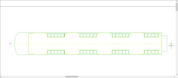
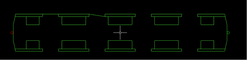
When you click the Train Carriage button on the Objects toolbar, you are asked to select its CAD (The CAD should leave spaces for the doors that will open at the platform, as shown above), then press Enter to continue.

Join points are two connection points (front and back), where carriages are linked together, to form trains. They are automatically snapped to the Longitudinal centre line of the carriage. You can specify their distance from the ends of carriages' CAD.
Every carriage has a name and a maximum capacity (optional), used to control the number of entities seeking to board. Entities do not enter carriages at capacity. Instead, they wait for the next train. Entities do not try to board other carriages, if their assigned carriage is full. If no maximum capacity is specified, entities board until the carriage is physically full, or the train dwell time is over.
Carriage Parameters
The Carriage properties dialog provides 2 data fields for naming carriages; Name and Notes (optional)

The Name is not optional, and is assigned a default name for a new Carriage. Notes are optional and can be anything you desire, usually additional details about the Carriage (manufacturer details, track gauge, gross weight etc).
Visual alert is given when a Carriage name is already used in a Catalog....
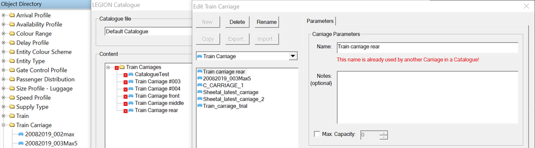
...and in the model:

Door Markings and Join Points
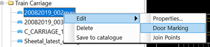
You can edit Train Carriage door markings and join points using Door Marking and Join Points options accessible in the Object Directory tab (expand Train Carriages and right-click the Carriage).
Click on Door Marking to view Carriage CAD to redraw the door positions.
A copy of the Carriage CAD appears in the model space at the mouse cursor:

Move the Carriage CAD to some unused model space and click to place it temporarily, for door editing.
All door marks are reset. Follow the output bar prompts to mark new door locations. Using end-point snaps can help:

Press <Enter> to complete. The Carriage in the model is updated.
Click on Join Points to reset and adjust the Carriage Join positions

A copy of the Carriage CAD appears at the mouse cursor:
Move the Carriage CAD to some unused model space and click to place it temporarily, for join point editing.
Follow output bar prompts to set new join points.

On completion, the Carriage in the model is updated.
Train
 Trains are collections
of carriages, and carriages appear in trains in the order in which they are
added to them. For each carriage in a train, a
Reverse option is available to allow you to
align the opening side of the carriage to the platform regardless of its
originally set orientation.
Trains are collections
of carriages, and carriages appear in trains in the order in which they are
added to them. For each carriage in a train, a
Reverse option is available to allow you to
align the opening side of the carriage to the platform regardless of its
originally set orientation.
When you click the Train button on the Objects toolbar, it opens a window in which you may define new trains. You may then add or delete carriages and set their orientation, using the Reverse check box. The Capacity set during carriage definition is also displayed here.

Service
 A
Service represents a particular train system,
for example:
A
Service represents a particular train system,
for example:
- London-to-Birmingham - Platform 1 - Virgin Trains, or
- London-to-Birmingham - Platform 1, West Midlands Trains.
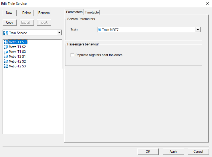
When the Service button on the Objects toolbar is clicked, a dialog opens, in which you define new services, or edit existing ones. In a service's Parameters tab, you must associate a Train with the Service. You can also choose whether to populate alighters near Train doors, or randomly throughout the Carriages. When Populate alighters near the doors is off, alighters are populated randomly throughout the Train interior. Alighting may be impeded by passengers staying on the Train. When on, alighters are populated so they are the nearest passengers to the doors, enabling a less impeded alighting behavior.
The Timetable tab is designed to define arrival time, number of alighters, number of stayers, and the Effective Door Open Time (EDOT), in seconds. When entering alighters' properties (by double-clicking in the cell in the alighters column), the Service instance properties window opens, so you may specify Entity/Supply Type, Population (number of entities), Passenger distribution and passengers' Final Destinations. Stayers' cells are similar, though without Final Destinations.


Platform
 Platform defines a CAD region in the model, in
which entities' behaviour is modified, based on train arrival and departure
events. Since a platform cannot be a Final Destination, entities cannot be
directed to
Platform objects. To direct entities to navigate
to a platform, they must have a
Service that is associated with the platform set
as their Final Destination.
Platform defines a CAD region in the model, in
which entities' behaviour is modified, based on train arrival and departure
events. Since a platform cannot be a Final Destination, entities cannot be
directed to
Platform objects. To direct entities to navigate
to a platform, they must have a
Service that is associated with the platform set
as their Final Destination.

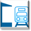
Define Platform Edge
You must identify the CAD elements that make up a platform edge. The simplest platforms are straight, needing only selection of a single line segment. Polylines may also be used, to represent curved platforms. Since selected CAD defines the edge alone, rather than the whole platform, selected CAD may not be closed, overall (i.e., form a rectangle, square, pentagon, or other polygon). Entered CAD is checked and if it does not form a continuous line, an Error is raised and the user must redefine it.
Once a valid CAD selection has been made, there is a prompt to simplify the platform edge, from which superfluous elements may be removed:
- Simplify the platform edge: Set maximum vertex-to-edge distance
Vertex-to-edge distance refers to the distance vertices on user-selected lines may be from the simplified platform edge. Here, you must enter a number with 0.0 metres representing no simplification and gradually increasing numbers representing gradually more simplified platform edges, until a single, straight line is reached. Press Enter to proceed. The background has been set to black in the following screen shots to aid visualisation.
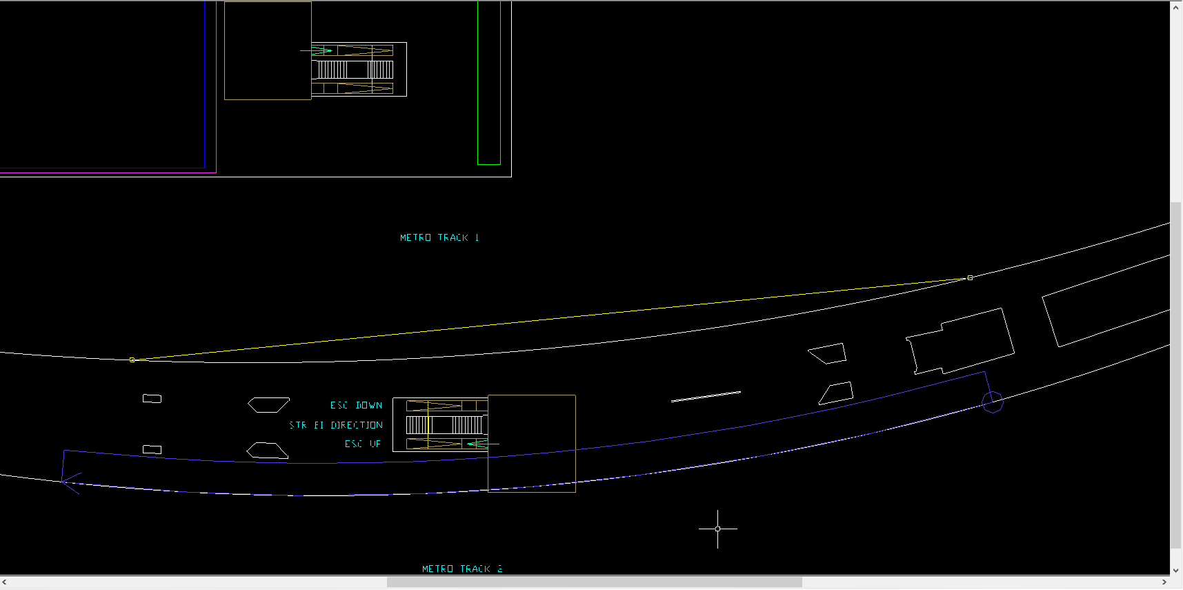

Yellow Line
To specify the "yellow line", first hover the mouse over the platform edge. The edge CAD is highlighted thick red.

Click on the red line to start setting the yellow line location. Then move the mouse away from edge to set the yellow line distance.
Click again to complete yellow line placement.
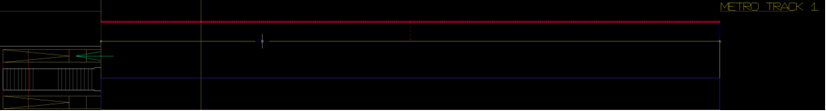
Platform Area
Next, you are shown:
- Back of platform: Set, or type, distance.
Here, you set the platform area, either by typing a platform depth, or by selecting and dragging a segment of the platform edge (highlighted when the mouse hovers over it). This is the area that entities wanting Services from this Platform will head to and wait in, before boarding.
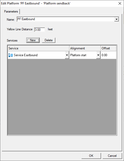
Platform-Service Pairing
Every Service is associated with a Platform, so that entities assigned Services as Final Destinations have targets to go to. To link a Platform and Service, right-click on the Platform and select Edit Platform from the context menu, then press New to add a new Service and complete its Properties. Alignment sets a reference point on the Platform, against which the points at which Train heads stop are determined. Offsets determine how far back (for positive input), or forward (for negative input, e.g., if part of the train is beyond the start of the Platform) from this reference point Trains stop. The Service is used as an entities' Final Destination, assigned either in the OD Matrix sheet of the Data Template, or manually in LEGION Model Builder